Zero Beat Ckt
I seem to get quite a few questions about this circuit. I should make it plain that I have never built the circuit here since I can easily zero beat within several Hz by ear. Thus I know little about it. I would suggest if you have questions about the circuit that you contact the hams mentioned below who have built and used the circuit. I don't want to publish their emails here to avoid having spambots mine them, but you can get the contact info from QRZ.com, I'm sure.
Some of the hams who have built this circuit found it very helpful, and provided comments and pictures that I want to share with you. First I'll describe the circuit, then present their info with the latest contributor at the top.
The original circuit and info is from a letter sent to me by W6OWP (now a Silent Key) several years ago.
"Randy Henderson's (WI5W) article in March 1992 QST (Do You Know Where Your Signal Is?) eloquently described a long-standing shortcoming in contemporary transceiver design.
As Randy pointed out, many transceivers set the CW transmit off-set equal to the set's sidetone frequency. But it was left to the operator how to match incoming signals to the sidetone for one-frequency QSOs -- an awkward and time-consuming procedure.
If yours is one of these (check your manual), a simple visual indicating circuit can be assembled to take advantage of the offset/sidetone relationship. A 567 decoder chip set to the transceiver sidetone frequency drives an LED. Audio from the transceiver speaker line is applied to the 567 input. The LED lights when an incoming signal is tuned to match this frequency. The RIT and XIT must be OFF for initial tuning.
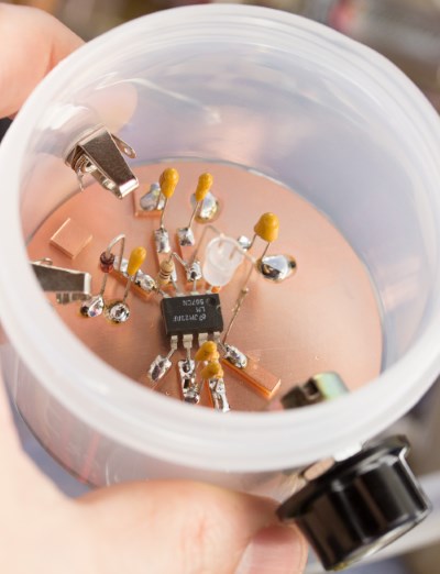
The few components required are shown in the accompanying diagram, and also listed below with Radio Shack part numbers. R2 sets the decoder frequency. A 35mm film container was used as the housing for the indicator.
If your transceiver is one of the few which doesn't match offset to sidetone, the circuit is still applicable. However, the offset must first be determined, then R2 adjusted accordingly.
A more detailed discussion of this use of the 567 appeared in the December 1990 "73" magazine."
R1 - value depends on DC voltage available. For 13.5V use a 470-ohm 1/4w, for 9V use a 180-ohm 1/4w.
R2 - 10K-ohm potentiometer RS #271-282
R3 - 470-ohm 1/4w resistor RS #271-1317
C1 - 1.0 Mfd tantalum RS #272-1434
C2,C4,C5,C6 - 0.1 Mfd tantalum RS #272-1432
C3 - 0.47 Mfd tantalum RS #272-1433
1 6.2V zener diode
1 8-pin IC socket RS #276-1995
1 Yellow LED RS #276-021
Except for the LM567 IC, all parts are currently available at Radio Shack. The 567 is a common, inexpensive IC and available from any outlet stocking a general supply of IC's. NOTE: With many Radio Shack stores closing because of the poor economy the past few years (2012-2015), you may have to search elsewhere for the parts. Some good Internet sources may be found in my Homebrew/Parts links.
Use tantalum capacitors for stability. The two 0.1 Mfd in parallel at C5 and C6 are to provide a total of 0.2 Mfd since Radio Shack does not stock 0.2.
Audio input comes from the transceiver speaker line.
The DC source is usually from an accessory voltage jack on the transceiver. The value of the series resistor will depend on voltage available.
Adjust the variable resistor using transceiver sidetone, decreasing level to the minimum value that will light the LED.
Be sure to provide a ground return for the DC and Audio inputs."
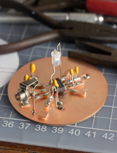
From Daniel HJ4DEI
"Just to let you know I built your zero beat circuit, I really enjoyed building it and it works amazingly well. My old TS440 with no filters has a bandwidth of about 1200Hz so your circuit really helps me a lot zero beating the other station. I went with a manhattan style construction.
Here are some pictures."
From Steve KC2SIZ
"Just wanted to let you know that I built your Zero Beat indicator circuit. Attached is an image of the finished product. I have been running it off 12v or so. I find that it works very well. I built it to use with a Ten Tec Eagle, which (somewhat surprisingly) does not have a spot tone or any other kind of zero beat indicator. My only quibble with this indicator thus far is that it requires a lot of audio gain. In order for it to work, I have to turn up the volume on my Eagle so that it is louder than I am used to. I will see what I can do to make it a little more sensitive. Changing the value of the R1 resistor (currently 470 ohms) might help with this? We will see. It's a handy little circuit though and my thanks to you for making it available. I'm sure it will see a lot of use in my shack! Thanks and 73! Steve KC2SIZ"
I suppose a simple one transistor or IC audio amplifier between the rig output and the circuit should do the trick if changing R1 doesn't work.
From Allen AE7TG
Allen AE7TG (NAQCC #3947) has posted a very informative article including pictures here describing his unit.
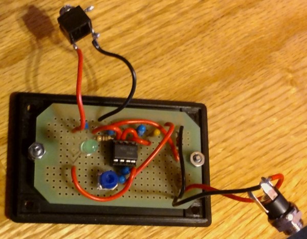
From Elwood WB0OEW
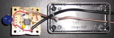
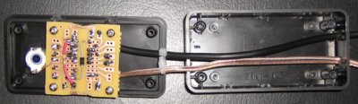
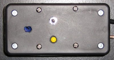
"Hello John, I want to thank you for posting the zero beat tuning aid circuit. I have been building it over the past few weeks and I'm now finished. I have attached a few photos. I did not try to miniaturize it very much, the box is about 1x2x3, about as small as I feel comfortable working. It has two connections to the radio, one for audio and one for 12V. I have to say it works very well. I am not confident tuning by ear and this little gem really relieves my worries about not tuning close to a station."
Elwood added these tips in a later email:
"Calibrate the potentiometer using your built in side tone. Start at one end and turn slowly until it (LED) comes on. Mark that location. Then start at the other extreme and come back the other way until it comes on again. Mark that location then position the pot to split the difference.
I added a momentary contact power switch so it only draws current for the few seconds needed to tune up. Just hold the button and tune until the LED pulses in step with the code with which you want to zero beat. Code at other frequencies near by will not confuse it.
For maximum accuracy, turn the volume down until the LED just registers the code. The higher the volume, the broader the response from the circuit."
Now here are the pictures of Elwood's unit.